Sometimes there is no need to send the entire range of voltages from a sensor to the
analog-to-digital converter (ADC). Instead, many times a sensor is used simply as a
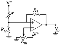
switch. Figure 40 contains a circuit called a comparator which takes an analog sensor
voltage and compares it to a threshold voltage, ![]() . If the sensor's voltage is greater
than the threshold, the output of the circuit is maximum (typically 5V). If the sensor's
output is less than the threshold, the output of the circuit is minimum (usually 0V). The
threshold voltage is set by adjusting the potentiometer labeled
. If the sensor's voltage is greater
than the threshold, the output of the circuit is maximum (typically 5V). If the sensor's
output is less than the threshold, the output of the circuit is minimum (usually 0V). The
threshold voltage is set by adjusting the potentiometer labeled ![]() . The output of
the sensor can also be reduced by using the resistor divider network as shown if desired.
Notice that the circuit has a positive feedback resistor
. The output of
the sensor can also be reduced by using the resistor divider network as shown if desired.
Notice that the circuit has a positive feedback resistor ![]() which assures that the
output of the comparator will swing quickly and completely from maximum output to
minimum output (also called ``rail to rail'').
which assures that the
output of the comparator will swing quickly and completely from maximum output to
minimum output (also called ``rail to rail'').
Example - Using an FSR as a Switch
An example of when this might be useful is in the case of the force sensing resistor. As depicted in Figure 6, typical force sensing resistors exhibit a region in which the resistance varies rapidly in response to a rather small variation in force. The force which defines this ‘knee' in the force vs. resistance curce is known as the break force. This behavior can be used to create a switch out of an FSR. This type of behaviour might be useful in devices such as membrane style keypads.
Figure 40: An FSR in a Switch Configuration, Using a Comparator
Figure 40 shows a circuit which implements a switch based upon a force sensing
resistor. The variable resistor, ![]() is used to set the sensitivity of the switch.
is used to set the sensitivity of the switch.
Motivation
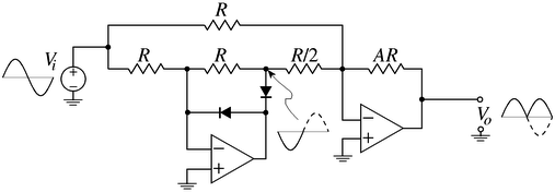
Sometimes, even though a sensor's output is an extremely complex waveform, only the energy of the waveform is needed. This is accomplished by rectifying the waveform (taking the absolute value) and then smoothing (lowpass filtering) the result. This process is shown in the circuit below.
Figure 41: Energy to Voltage Conversion
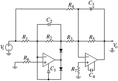
Notice that the output is a rectified version of the input. Figure 42 adds a couple capacitors to the above circuit to smooth the output.
Figure 42: A Complete Energy Measurement Circuit
Example - EMG Measurement Using an Electrode
As was discussed previously, the output of the electrode is a voltage waveform that measures underlying neural activity. Many times, when measuring the EMG, the complex waveform that is created by many neural motor units firing is irrelevant. What is of interest is the average energy caused by the muscle exertion. The circuit shown in Figure 42 is used to obtain this energy. The capacitors are usually chosen to smooth off changes faster than 5-10Hz.